

There's a kind of frustration that comes from a yard full of lights that almost work. One path light is dead. Three spotlights glow half as bright as the rest. The back run quit on Tuesday and nobody knows why. When this happens — and it happens to every system eventually — most people start guessing: new bulbs, new fixtures, maybe a whole new transformer. I used to guess too, and wasted real money replacing perfectly good parts. Then I learned how to test landscape lighting with a multimeter, and honestly, everything changed. A basic meter costs less than a single replacement fixture, and in fifteen minutes it will tell you which part of your system is healthy and which part is hurting — the transformer, the cable, or the fixture — instead of leaving you swapping parts on hunches. In this guide I'll walk you through the process the way I do it in my own yard: the four meter settings that matter, how to test voltage at the transformer and at each fixture, how a continuity test finds cable breaks you can't see, and how to read the numbers like a pro. No electrician required, I promise.
The Short Answer
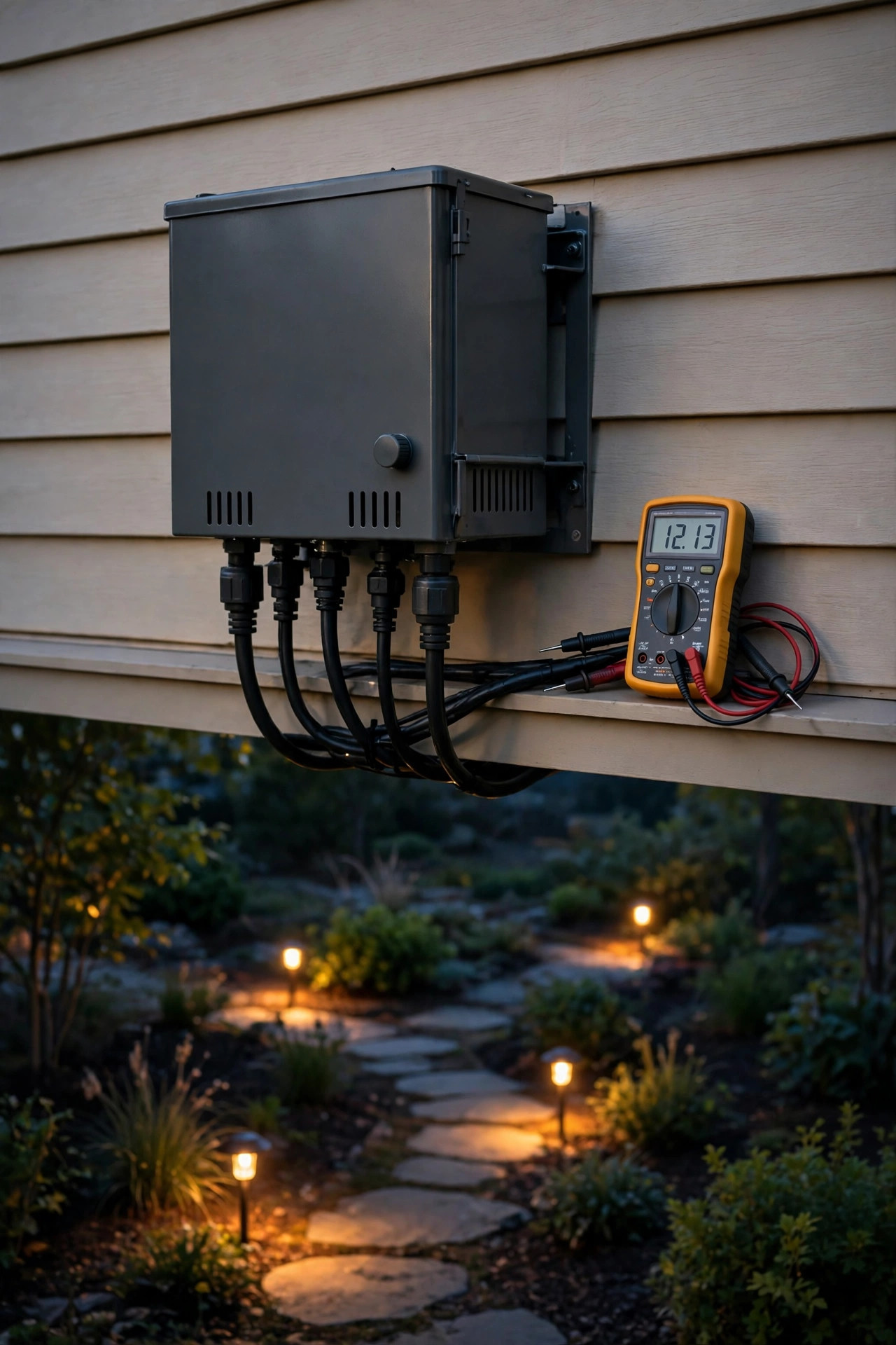
To test landscape lighting with a multimeter, set the dial to AC volts and touch the probes to your transformer's output terminals — a healthy 12-volt tap reads roughly 12 to 13.5 volts. Then test again at the nearest fixture and the farthest one: fixtures want at least 10.8 volts to shine properly, and a big gap between the first and last reading means voltage drop. For a completely dead run, unplug the transformer, switch the meter to continuity, and test the cable — a beep means the wire is whole, while silence or an "OL" reading means there's a break. Three tests, fifteen minutes, zero guessing.
Why Testing Beats Guessing When Lights Misbehave
Here's what most people don't realize: a landscape lighting system only has a handful of parts that can actually fail. There's the transformer, the buried cable, the connectors, and the fixtures with their bulbs. That's it. The trouble is that every one of those failures looks almost identical from the back porch — lights that are dim, flickering, or just plain out — while the fixes range from free (resetting a tripped outlet) to a couple of dollars (a new connector) to a few hundred (a transformer you may not even need).
A multimeter breaks that tie. Instead of wondering, you divide the system into three zones — power source, cable runs, and fixtures — and test each zone in order. Reading good voltage at the transformer but nothing at the first fixture? The problem is in the first few feet of cable, not the transformer. Good voltage at a dead fixture's socket? The transformer and cable are innocent; it's the bulb or fixture. Voltage that fades steadily down the run? That's voltage drop, a wire-size problem, not a parts problem.
In my experience, nine times out of ten the culprit turns out to be a two-dollar connector or a cable nicked by a garden edger — the cheap stuff. Two or three meter readings will point you straight at it, and you'll fix the actual problem in an afternoon instead of rebuilding a healthy system one expensive guess at a time.
What You Need Before You Start
The good news is that this is a very short shopping list. The star of the show is a basic digital multimeter. An auto-ranging model is the easiest for beginners because it picks the right scale for you, and it only costs a little more than a manual-range one. Before you head outside, put a fresh battery in the meter — a dying meter battery is a sneaky troublemaker that produces drifting, nonsense numbers that will send you chasing faults that don't exist.
Beyond the meter, gather a small flat-head screwdriver for the transformer terminals, a pair of wire strippers and cutters in case a repair is waiting for you, and a small handful of waterproof gel-filled connectors so you can fix a bad connection on the spot instead of making a second trip. Alligator-clip adapters for your test leads are a quiet luxury: they grip terminals and wire ends so you can work hands-free, which matters when you're crouched at the far end of a dark garden bed.
Finally, bring your phone or a scrap of paper and write down every reading, fixture by fixture. Voltage numbers that look "fine-ish" in the moment become a clear map of your whole system when you can compare them side by side. Oh — and a headlamp. You'll want the system under its real working load while you test, and that means working in the dusk alongside your lights.

Safety First: Low Voltage Is Forgiving, Not Harmless
One of the joys of a 12-volt system is that the outdoor side is genuinely beginner-safe — the voltage at your fixtures is far too low to give you a meaningful shock under normal conditions. But "forgiving" is not the same as "rule-free," and a few habits will protect both you and your meter.
The most important rule in this entire guide: unplug the transformer before any continuity or resistance test. Those tests work by sending a tiny signal from the meter's own battery through the wire. Do it on a live circuit and the readings are garbage at best; at worst, you blow the meter's internal fuse or damage the meter outright. Live circuits are for voltage tests only.
Second, leave the 120-volt side alone. Your transformer plugs into a household outlet, and if there's any suspicion the problem lives there — scorch marks, a buzzing transformer, a breaker that keeps tripping — that's electrician territory, full stop. What you can safely do is check the outlet itself: nine times out of ten a "dead transformer" is just a tripped GFCI. Press the little reset button on the outlet before you test anything else. Seriously. Check that first.
Also, never probe a transformer with the meter set to amps — the current setting is essentially a dead short between the probes and will pop the meter's fuse instantly. And before you dig anywhere to reach a suspect cable, work carefully and shallowly: your own low-voltage cable is harmless, but sprinkler lines and other utilities may share the bed.
The Only 4 Multimeter Settings You'll Ever Use
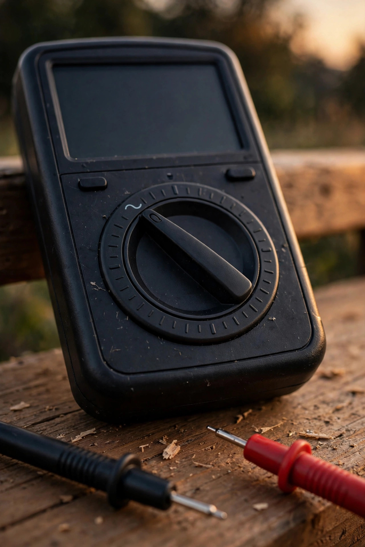
A multimeter dial looks intimidating, with its alphabet soup of symbols, but landscape lighting only ever asks for four settings. Learn these and you can ignore the rest of the dial forever.
AC volts (V~ or VAC) is the big one. Your transformer takes 120-volt household AC power and steps it down to low-voltage AC, so everything on the lighting side of the system is alternating current. Voltage testing — at the transformer, at fixtures, anywhere the system is live — happens on this setting. On a manual-range meter, choose the 200-volt AC range; on an auto-ranging meter, just turn to V~ and let it think.
Continuity (usually marked with a little sound-wave symbol, sometimes sharing the resistance position) makes the meter beep when there's a complete path between the probes. It's your broken-wire detector, and it's used only with the power OFF and the transformer unplugged.
Resistance (Ω) is continuity's more precise sibling. Instead of a beep, you get a number, which is useful for testing halogen bulb filaments and judging how much resistance a long or corroded cable run has picked up.
DC volts (V⎓) is the only setting you won't use on a wired system — it belongs to solar lights, whose panels and batteries are DC. If a solar fixture ever needs testing, this is the one.
Last setup detail: black probe in the COM jack, red probe in the VΩ jack. The red lead does not belong in the amps jack for anything in this guide.
Step-by-Step: Test Landscape Lighting With a Multimeter at the Transformer
Every diagnosis starts at the power source. If the transformer isn't putting out proper voltage, nothing downstream matters, so we test here first.
1. Turn the system fully on. Set the transformer to manual ON if it has one. If it runs on a photocell, cover the little eye with a piece of electrical tape so it thinks night has fallen. A timer that's "off" right now will give you a transformer that reads zero volts and looks dead when it isn't.
2. Open the transformer cover and find the terminals. You'll see a common terminal (labeled COM) and one or more voltage taps — a single tap labeled 12V, or several on a multi-tap unit: 12, 13, 14, 15.
3. Set the meter to AC volts. Touch the black probe firmly to the COM terminal screw and the red probe to the 12V tap screw. Press on clean metal, not on corrosion or dirt.
4. Read the number. A healthy transformer reads at or slightly above the tap value — typically 12 to 13.5 volts on the 12-volt tap, since taps read a touch high with a light load.
5. Interpret zero volts correctly: check the GFCI outlet, confirm the outlet has power with something you trust (a phone charger works), and double-check the timer and photocell before blaming the transformer.
6. If voltage reads far below the tap value — say 8 volts on the 12-volt tap with the lights on — disconnect one cable run at a time and watch the meter. If the reading jumps back to normal when a run is removed, that run has a short or an overload dragging the whole system down, and you've just found your problem zone.
Write the number down. This is your system's "supply" figure, and everything else gets compared against it.

Step-by-Step: Testing Voltage at the Fixtures
With the transformer proven, walk the system. The pattern of readings from fixture to fixture is what turns a mystery into a map.
Start with the fixture closest to the transformer. The easiest test point is the fixture's socket: pop the bulb out (give it a minute to cool if it's halogen) and touch your probes to the two socket contacts — for a bi-pin bulb, that's the two little holes or contacts the pins slide into. Set to AC volts, system on. Your first fixture should read within about half a volt of what you measured at the transformer. A big drop this close to the source means a corroded main connector or damaged cable right at the start of the run.
Then walk to the very last fixture on the same run and repeat. This is the most informative single reading in your whole system, because the last fixture lives at the end of every inch of cable and feels every bit of resistance along the way. Jot down both numbers — the gap between them is your voltage drop, and we'll decode it in the next section.
While you're out there, test any fixture that's misbehaving. A dead fixture with a healthy 12 volts at its socket has a bulb or fixture problem, and you can stop digging up cable. A dead fixture with zero volts at the socket means power never arrived — the fault is upstream in the cable or a connector, and the fixture itself is probably fine.
One honest note: socket readings with the bulb removed are unloaded readings, so they're slightly optimistic. For troubleshooting, that's fine — you're comparing fixtures against each other and against the transformer, and the pattern tells the story.

How to Read Your Numbers: What Healthy Voltage Looks Like
Numbers only help if you know what they're supposed to be, so here are the benchmarks I use in my own yard.
At the transformer: the tap value to about a volt above it. Twelve to 13.5 volts on the 12-volt tap is healthy. At the first fixture: within roughly half a volt of the transformer reading. At the last fixture: at least 10.8 volts. That's the classic floor — halogen bulbs below it turn visibly dim and orange, and while LEDs tolerate a wider range (many are rated from 9 to 15 volts), they still look their best at 11 volts and up. Total drop across a run: under about 1.5 volts is healthy. Once the gap between first and last fixture passes 2 volts, you'll see the brightness "slope" with your own eyes.
If your last fixture is starving, the fix is almost never a new fixture — it's the wiring. Thicker cable, splitting one long run into two shorter ones, or stepping up to a higher transformer tap are the proven cures, and I walk through all of them in my guide to landscape lighting voltage drop.
One more subtlety: test with all the lights on. Voltage drop grows with load, so a run that reads a respectable 11.8 volts feeding two fixtures may slump to 9.5 when all ten are lit. Loaded readings are the truth; unloaded readings are the brochure. And trust your eyes alongside the meter: if the last light on the path looks warmer and more amber than the first, the numbers will confirm what the color already told you.

Continuity Testing: Finding Breaks You Can't See
Voltage tests tell you where power stops. A continuity test tells you whether a cable is whole — and it finds breaks that are buried, hidden under mulch, or inside a fixture whip where your eyes can't go.
First, the non-negotiable setup: system OFF, transformer unplugged, and the cable pair disconnected from the transformer terminals. You want to test the cable alone, not a path that wanders through the transformer or the fixtures.
The basic loop test works like this. Go to the far end of the run and twist the two conductors of the cable together. Back at the transformer end, set the meter to continuity and touch one probe to each conductor. A beep — or a very low resistance reading, around an ohm or less for a typical run — means the copper is continuous all the way out and back. Silence, or an "OL" (overload/open loop) display, means the circuit is broken somewhere along that run. A healthy 100-foot loop of 12-gauge cable reads roughly a third of an ohm of copper resistance, so if your meter shows several ohms instead, suspect a corroded connection adding invisible resistance even though the wire itself is intact.
Now untwist the far end and probe across the pair again. With the fixtures disconnected, this should read OL — the two conductors should never touch. A beep here means a short: the conductors are touching somewhere, often where a shovel nicked the insulation. Be aware that fixtures left connected will confuse this test, because halogen filaments and LED drivers create their own internal paths. For a clean answer, disconnect the fixtures, or at least know that a low-but-not-zero reading with fixtures attached usually just means you're measuring through a bulb.

How to Test Landscape Lighting With a Multimeter When a Whole Run Goes Dark
When an entire run is out but the transformer tests fine, the break is somewhere along that cable — and the half-split method finds it without excavating your whole garden. The idea is simple: test the midpoint, and whichever half fails, split that half again. Three or four rounds narrow a 100-foot mystery down to a few feet of cable.
Work with the power on for the first pass. Find a fixture or junction near the middle of the run, disconnect the downstream side, and test voltage on the cable feeding that point. Voltage present at the midpoint? The break is beyond it — reconnect and move your test point halfway toward the end. No voltage? The break is between the transformer and where you're standing, so move halfway back toward the house. Each test chops the suspect territory in half.
Then switch to a power-off continuity test on the guilty segment to confirm before you dig. In my experience, the break almost always turns up somewhere with a story: where the lawn gets aerated, where a shovel went in for a new plant, where a stake got yanked, or where a connector pulled apart over a winter of freeze and thaw. Keep an eye out for moisture tricks, too — a run that works when dry and dies after rain has nicked insulation that's letting water bridge the conductors.
When you do replace a damaged section, match the original wire gauge or go one size thicker, and make the repair with gel-filled direct-bury connectors. If you're unsure which gauge a longer replacement needs, my landscape lighting wire gauge guide has the sizing math in plain English.

Testing Fixtures, Bulbs and Those Pesky Connectors
Individual dead fixtures are the most common complaint of all, and they're the quickest to diagnose. System on, meter on AC volts, bulb out, probes on the socket contacts.
Twelve volts at the socket and a dark fixture means the problem is in your hand, not in the ground. For a halogen bulb, you can confirm with a power-off resistance test across its two pins: a good filament shows a low reading, just a few ohms, while a burned-out filament reads OL. LED bulbs are a different story — their internal drivers make resistance readings meaningless, so don't even try. The honest LED test is substitution: swap in a bulb you know works. If the known-good bulb lights, the old bulb is done. If it doesn't, and the socket voltage was fine, the fixture's internal wiring or socket contacts have corroded past saving.
Now, the connectors. I will say this plainly: in my experience, pierce-style connectors are the number one failure point in home landscape lighting. They bite through the cable insulation with little metal teeth, and over a few seasons moisture creeps in, the teeth corrode, and the connection quietly dies — while looking perfectly fine from outside. The test is easy: measure voltage on the cable just before the connector, then at the fixture just after it. Good voltage in, nothing out? Replace the connector with a gel-filled direct-bury type. It costs a dollar or three and takes five minutes, and it will outlast the fixture it feeds.

Symptom Decoder: What Your Readings Are Telling You
Once you've taken a few readings, patterns emerge. This is the cheat sheet I keep in my head whenever a system acts up:
| What you see | What the meter says | Likely cause | The fix |
|---|---|---|---|
| Every light is out | 0V at the transformer | Tripped GFCI, timer off, or dead outlet | Reset the GFCI, check the outlet and timer |
| Every light is out | Good voltage at transformer, 0V at first fixture | Main cable cut or failed connector near the transformer | Inspect the first few feet of cable |
| One whole run is out | Other runs read fine | Break or corroded connector on that run | Half-split test the run |
| End lights dim and amber | Last fixture below 10.5V | Voltage drop on a long or thin run | Thicker wire, split the run, higher tap |
| Lights flicker | Voltage jumps when you wiggle the cable | Loose or corroded connection | Remake the connector |
| One light is out | 12V at its socket | Dead bulb or fixture | Swap-test the bulb, replace fixture |
| Works dry, dies after rain | Normal readings on a dry day | Nicked insulation letting water in | Find the damage, splice with a gel connector |
Notice what isn't on this list: "replace the transformer." Transformers do fail, but far less often than everything above them on that table — and now you can prove which one it is in minutes instead of paying to find out by elimination.
What It Costs in 2026
Testing your own system is one of the cheapest diagnostic bargains in home ownership. A basic manual-range multimeter runs $12 to $20, and a decent auto-ranging model — the one I'd steer a friend toward — is $25 to $40. An alligator-clip lead set adds $8 to $15 and pays for itself in convenience the first evening you use it. If your tests lead to repairs, waterproof gel connectors are $1 to $3 each, and a spool of replacement cable costs a fraction of what one new fixture runs.
Compare that with the alternatives. A landscape lighting company's diagnostic visit typically starts around $75 to $150 before a single part is replaced, and an electrician's service call is more. Even the guess-and-replace route adds up fast: fixtures run $15 to $60 apiece, and a transformer is $60 to $250 — real money to spend on a hunch when a $30 meter would have told you the truth first.
And the meter isn't a one-evening rental. It'll test doorbell transformers, check batteries, verify outlets before you plug in holiday lights, and settle a hundred little "is it dead or is it the power?" arguments around the house for years. Mine has absolutely earned its drawer space.

5 Multimeter Mistakes That Give You Lying Numbers
A meter never lies on purpose, but it will faithfully report the wrong test if you ask it the wrong way. These are the traps I see beginners (and, once upon a time, myself) fall into.
1. Testing in DC mode. This is the classic. Your system is AC, and a meter set to DC volts will shrug and show something near zero across a perfectly healthy transformer. If every reading looks dead, check the dial before you check the yard.
2. Running a continuity test with the power on. Beyond giving you meaningless numbers, it can blow the meter's fuse. Continuity and resistance always mean: transformer unplugged, no exceptions.
3. Probing through dirt and corrosion. A film of grime on a terminal acts like a resistor between your probe and the truth, so readings come back mysteriously low. Scrape to clean, bright metal before you trust a number.
4. Testing while the timer or photocell has the system off. Zero volts at noon doesn't mean a dead transformer — it may just mean the lights are scheduled to be off. Override to manual ON, or tape over the photocell, before concluding anything.
5. Trusting resistance readings on LED bulbs. LED drivers don't behave like simple filaments, so an ohms test tells you nothing useful. Swap-test LEDs with a known-good bulb instead. And a bonus sixth, because it got me once: if your numbers drift wildly from second to second, replace the meter's own battery before you condemn anything in the yard.
When to Stop Testing and Call a Pro
I'm a enthusiastic DIY believer, and low-voltage troubleshooting is some of the safest, most satisfying diagnostic work a homeowner can do. But part of doing it well is knowing exactly where the DIY border runs.
That border is the 120-volt side of the transformer. If the transformer itself is buzzing loudly, hot, scorched, or tripping a breaker, unplug it and call an electrician — household voltage is not a learning playground. The same goes for a plug-in transformer that's proven dead and needs swapping with a hardwired unit: if wires are getting cut and joined on the house side, that's a pro's job.
Pros also earn their fee on true needle-in-a-haystack faults. If a run keeps failing tests but every accessible connector checks out, a lighting contractor's cable fault locator can pinpoint an underground break to within inches — equipment that costs more than most of us will ever save by owning it.
Everything else? Test away with confidence. My own habit is to make this fifteen-minute routine part of spring cleanup: transformer reading, first and last fixture readings, a wiggle test on the connectors. It catches corrosion and loosening a full season before they turn into dark walkways, and it pairs naturally with the cleaning and bulb checks on my outdoor lighting maintenance checklist.
Frequently Asked Questions
What setting do I use on a multimeter to test landscape lighting?
For a wired low-voltage system, use AC volts (marked V~ or VAC) for every live test — your transformer outputs alternating current, so a DC setting will misleadingly read near zero. Use continuity or resistance only for checking whether a cable or a halogen filament is intact, and only with the transformer unplugged. The DC volts setting has exactly one job in the yard: testing the battery and panel on solar lights.
What voltage should my landscape lights actually be getting?
At the fixture, the comfortable zone is about 10.8 to 12 volts while the system is on. Halogen bulbs below roughly 10.5 volts turn noticeably dim and orange, and while LED fixtures usually tolerate a wider range — many are rated 9 to 15 volts — they still look best at 11 volts or more. At the transformer, expect the tap value or a little above: 12 to 13.5 volts on the 12-volt tap is perfectly healthy.
Can I run a continuity test with the power on?
No — never. Continuity and resistance tests work by sending a small signal from the meter's own battery through the wire, so the circuit must be completely dead: system off, transformer unplugged, and ideally the cable disconnected from the terminals. Testing a live circuit gives you invalid readings and can blow the meter's internal fuse or damage the meter itself. Voltage tests are the only tests done with the power on.
My transformer shows 12 volts but the lights still don't work. Why?
Because voltage at the terminals only proves the transformer is alive — it says nothing about whether power can actually travel. If the main cable is cut or its first connector has corroded through, the meter still reads a cheerful 12 volts at the source while nothing reaches the yard. Test at the first fixture next: zero volts there points to the cable or connector between. One sneakier possibility is a high-resistance connection that shows voltage with no load but collapses the moment the lights draw current — which is exactly why you should always take fixture readings with the system switched on.
Conclusion
A multimeter turns landscape lighting repair from a guessing game into a fifteen-minute conversation with your own yard. Test the transformer for voltage, test the first and last fixtures to see how the power travels, and use continuity to prove whether a cable is whole — those three checks will corner nearly every fault a low-voltage system can develop. The next time a run goes dark, resist the urge to start buying parts. Learn to test landscape lighting with a multimeter once, and you'll never troubleshoot in the dark again — literally. When you're ready to put your newly healthy system to work, browse the lighting ideas and guides here for fresh ways to make it glow.